1.1 Basic Concepts
Ohm’s Law
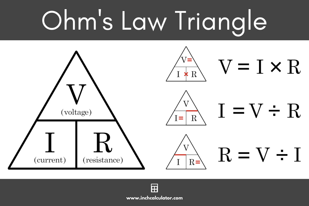
Ohm’s Law states that the current (I) through a conductor between two points is directly proportional to the voltage (V) across the two points and inversely proportional to the resistance (R).
Formula:
Ohm’s Law states that the current (I) through a conductor between two points is directly proportional to the voltage (V) across the two points and inversely proportional to the resistance (R).
Formula:
Electric Voltage, Current, Power, and Energy
Voltage (V): Potential difference between two points (measured in Volts).
Current (I): Flow of electric charge (measured in Amperes).
Power (P): Rate of energy transfer (measured in Watts).
Energy (E): Total work done (measured in Joules).
Voltage (V): Potential difference between two points (measured in Volts).
Current (I): Flow of electric charge (measured in Amperes).
Power (P): Rate of energy transfer (measured in Watts).
Energy (E): Total work done (measured in Joules).
Conducting and Insulating Materials
Conductors: Allow free electron flow (e.g., copper, aluminum).
Insulators: Resist electron flow (e.g., rubber, glass).
Conductors: Allow free electron flow (e.g., copper, aluminum).
Insulators: Resist electron flow (e.g., rubber, glass).
Series and Parallel Circuits
Series Circuit: Components connected end-to-end (same current, voltage divides).
Parallel Circuit: Components connected across common points (same voltage, current divides).
Series Circuit: Components connected end-to-end (same current, voltage divides).
Parallel Circuit: Components connected across common points (same voltage, current divides).
Star-Delta and Delta-Star Conversion
Used for simplifying complex resistor networks.
Star (Y) to Delta (Δ):
Delta (Δ) to Star (Y):
Used for simplifying complex resistor networks.
Star (Y) to Delta (Δ):
Delta (Δ) to Star (Y):

Kirchhoff’s Laws
KCL (Current Law): Sum of currents entering a node = Sum leaving.
KVL (Voltage Law): Sum of voltages in a closed loop = 0.
KCL (Current Law): Sum of currents entering a node = Sum leaving.
KVL (Voltage Law): Sum of voltages in a closed loop = 0.
Linear & Non-Linear Circuits
Linear: Follows superposition (Ohm’s Law holds).
Non-Linear: Does not follow superposition (diodes, transistors).
Linear: Follows superposition (Ohm’s Law holds).
Non-Linear: Does not follow superposition (diodes, transistors).
Bilateral & Unilateral Circuits
Bilateral: Current flows both ways (resistors).
Unilateral: Current flows one way (diodes).
Bilateral: Current flows both ways (resistors).
Unilateral: Current flows one way (diodes).
Active & Passive Circuits
Active: Contains energy sources (batteries, transistors).
Passive: No energy sources (resistors, capacitors).
Active: Contains energy sources (batteries, transistors).
Passive: No energy sources (resistors, capacitors).
1.2 Network Theorems
Superposition Theorem
In a linear circuit, the response (voltage/current) due to multiple sources is the sum of responses due to each source acting alone.
In a linear circuit, the response (voltage/current) due to multiple sources is the sum of responses due to each source acting alone.
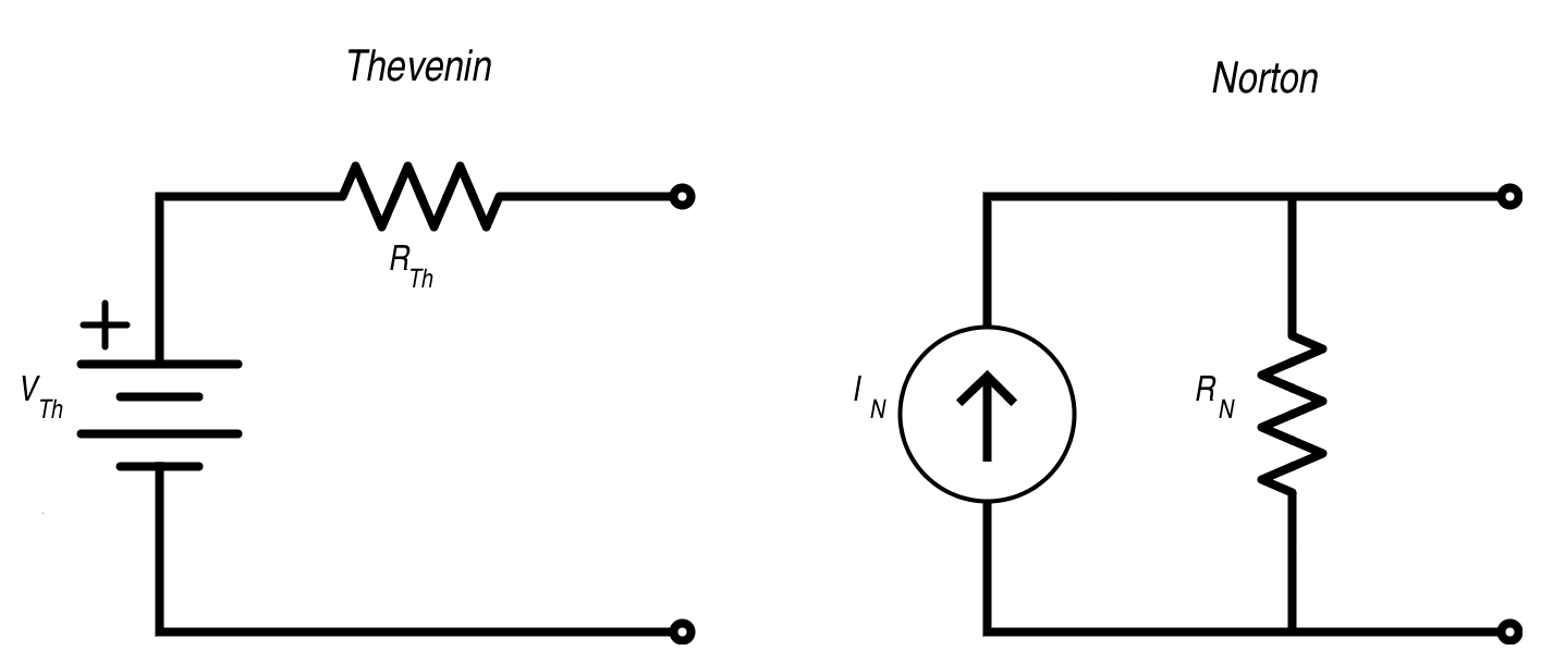
Thevenin’s Theorem
Any linear network can be replaced by an equivalent circuit with a voltage source (Vth) and series resistance (Rth).
Any linear network can be replaced by an equivalent circuit with a voltage source (Vth) and series resistance (Rth).
Norton’s Theorem
Any linear network can be replaced by an equivalent current source (In) and parallel resistance (Rn).
Any linear network can be replaced by an equivalent current source (In) and parallel resistance (Rn).
Maximum Power Transfer Theorem
Maximum power is transferred when load resistance equals source resistance.
Maximum power is transferred when load resistance equals source resistance.
R-L, R-C, R-L-C Circuits
R-L Circuit: Inductor resists current changes.
R-C Circuit: Capacitor resists voltage changes.
R-L-C Circuit: Exhibits resonance at .
R-L Circuit: Inductor resists current changes.
R-C Circuit: Capacitor resists voltage changes.
R-L-C Circuit: Exhibits resonance at .
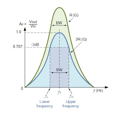
Resonance in AC Circuits
Series Resonance: Minimum impedance, maximum current.
Parallel Resonance: Maximum impedance, minimum current.
Series Resonance: Minimum impedance, maximum current.
Parallel Resonance: Maximum impedance, minimum current.
Active & Reactive Power
Active Power (P): Real power (Watts).
Reactive Power (Q): Stored power (VAR).
Apparent Power (S): .
Active Power (P): Real power (Watts).
Reactive Power (Q): Stored power (VAR).
Apparent Power (S): .
1.3 Alternating Current Fundamentals
Generation of AC
Produced by rotating a coil in a magnetic field (sinusoidal waveform).
Produced by rotating a coil in a magnetic field (sinusoidal waveform).
Peak, RMS, and Average Values
Peak Value: Maximum amplitude.
RMS Value: .
Average Value: .
Peak Value: Maximum amplitude.
RMS Value: .
Average Value: .
Three-Phase System
Three AC voltages 120° apart, used for efficient power transmission.
Image Reference:
Sinusoidal AC Waveform
Three-Phase Voltage Waveform
Three AC voltages 120° apart, used for efficient power transmission.
Image Reference:
Sinusoidal AC Waveform
Three-Phase Voltage Waveform
1.4 Semiconductor Devices
Semiconductor Diode
Characteristics: Forward bias (conducts), Reverse bias (blocks).
Applications: Rectifiers, clippers.
Characteristics: Forward bias (conducts), Reverse bias (blocks).
Applications: Rectifiers, clippers.
BJT (Bipolar Junction Transistor)
Configurations: Common Emitter, Base, Collector.
Biasing: Fixed, Emitter, Voltage Divider.
Configurations: Common Emitter, Base, Collector.
Biasing: Fixed, Emitter, Voltage Divider.
MOSFET & CMOS
MOSFET: Voltage-controlled device (high input impedance).
CMOS: Complementary MOSFET (low power).
Image Reference:
Diode I-V Curve
BJT Configurations Diagram
MOSFET: Voltage-controlled device (high input impedance).
CMOS: Complementary MOSFET (low power).
Image Reference:
Diode I-V Curve
BJT Configurations Diagram
1.5 Signal Generators
Oscillators
Generate periodic waveforms (sine, square, triangle).
RC Oscillator: Phase-shift, Wien bridge.
LC Oscillator: Hartley, Colpitts.
Crystal Oscillator: High stability.

Generate periodic waveforms (sine, square, triangle).
RC Oscillator: Phase-shift, Wien bridge.
LC Oscillator: Hartley, Colpitts.
Crystal Oscillator: High stability.
1.6 Amplifiers
Classification
Class A: Linear, low distortion.
Class B: Push-pull, efficient.
Class AB: Compromise between A & B.
Class A: Linear, low distortion.
Class B: Push-pull, efficient.
Class AB: Compromise between A & B.

Power BJTs & Tuned Amplifiers
Power BJTs: Handle high currents.
Tuned Amplifiers: Selects specific frequencies.
Power BJTs: Handle high currents.
Tuned Amplifiers: Selects specific frequencies.
Op-Amps
High-gain differential amplifiers (feedback-based).
High-gain differential amplifiers (feedback-based).